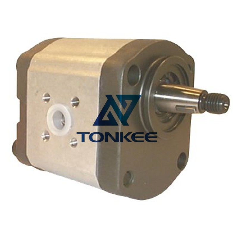
Type: The 5B1 40022fah is a hydraulic gear pump, which means it operates based on the principle of positive displacement.
It consists of two meshing gears, typically helical or spur gears, within a tightly sealed housing.
Flow Rate: This pump is designed to handle a specific flow rate of hydraulic fluid. The flow rate determines how much fluid the pump can deliver per unit of time, usually measured in gallons per minute (GPM) or liters per minute (LPM).
Pressure Rating: The hydraulic gear pump also has a specified pressure rating. This indicates the maximum pressure it can generate within the hydraulic system. Pressure is measured in pounds per square inch (PSI) or bars.
Materials: These pumps are typically constructed with materials that offer high strength and corrosion resistance. Common materials include cast iron, steel, or aluminum, depending on the application and required durability.
Mounting Options: The 5B1 40022fah pump can have various mounting options, such as flange, foot, or direct-coupled configurations.
This flexibility allows for easier integration into different hydraulic systems.
Working Principles:
Hydraulic gear pumps operate using the principle of positive displacement. Here's a simplified overview of how they work:
Gear Meshing: Inside the pump housing, there are two gears - a driving gear and a driven gear. These gears mesh together and rotate in opposite directions.
Suction Phase: As the gears rotate, they create a low-pressure area on the inlet side, allowing hydraulic fluid to be drawn into the pump through an inlet port.
Compression Phase: As the gears continue to rotate, they trap and compress the hydraulic fluid between the gear teeth and the pump housing.
Discharge Phase: The compressed fluid is forced out of the pump through an outlet port as the gears separate, generating hydraulic pressure.
Repeat: This cycle repeats continuously as the gears rotate, resulting in a consistent flow of pressurized hydraulic fluid.